I’ve been following Iñigo Quilez’s masterclass “Live Coding ‘Happy Jumping’”, where he implements a raymarching shader in ShaderToy that generates a scene with a jumping monster walking across a peculiar terrain. For him it was an animation exercise, since he applies principles like squash and stretch.
For me, however, it’s an opportunity to learn how these three-dimensional scenes are built using shaders, without 3D models, just math and code. With this article I try to expand on some concepts to make them clearer and dig a bit deeper into the subject.
Watch the “Happy Jumping” shader on ShaderToy
Raymarching
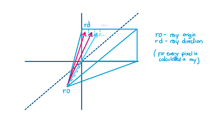
According to Iñigo Quilez, raymarching can be understood as a technique for exploring a three-dimensional scene with rays. Each pixel on the screen generates a ray that travels into the virtual space and searches for the surfaces present in the scene.
At each iteration a Signed Distance Function (SDF) is evaluated, a function that returns the signed distance to the nearest surface. This value determines how far the ray can safely advance without passing through any object. When the surface is far away, the steps can be large; as the ray gets closer to an object, the increments progressively shrink, increasing the precision of the calculation.
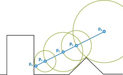
Thanks to this mechanism, it’s possible to represent complex scenes defined solely through mathematical functions, without the need for meshes, vertices, or traditional geometric structures.
// This normalize the coordinates from (-aspectRatio,-1) to (aspectRatio, 1)
vec2 p = (2.0*(fragCoord+offset)-iResolution.xy) / iResolution.y;

vec3 ro = vec3(0.0,0.0,2.0);
vec3 rd = normalize(vec3(p,-1.5));

// if ray doesn't hit anything value -1
vec4 res = vec4(-1.0, -1.0, 0.0,1.0);

float t = 0.0;
for(int i = 0; i < 128; ++i)
{
	vec3 pos = ro + t* rd;
	// map function will return a distance that is secure to advance
	vec4 h = map(pos,atime);
	t+=h.x;
}
Raymarching pseudocode
Now then, how is that maximum advance distance calculated without passing through the different objects? There’s no single answer: depending on the type of object, there are different formulas. A sphere would be an example of a simple case:
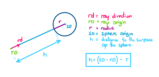
The maximum distance (h) we can advance without passing through the sphere is the distance between the ray origin and the sphere’s center, minus its radius.
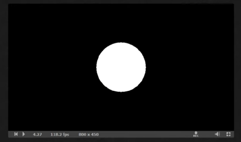
With this we can already start drawing something: as soon as we know we’ve hit the sphere, we can show it on screen and even start lighting it.
Calculating normals
To calculate the scene’s lighting, we first need to calculate the normals of the objects the ray collides with. Once we know at what distance t the collision happens, we can find the exact point on the surface, and from there calculate the normal.
vec3 pos = ro + t*rd;
vec3 nor = calcNormal( pos, time );
Since the map() function is continuous, the direction in which the distance changes fastest (its gradient) coincides with the surface normal. To approximate that gradient, we take the collision point and shift it slightly along each axis (x, y, z), calculating the difference in distance between shifting the point to one side and to the other (central finite differences). The normalized result gives us the direction of the normal.
vec3 calcNormal( in vec3 pos, float time )
{
	float e = 0.0001; // small offset

	float dx = map( pos + vec3(e,0,0), time ).x - map( pos - vec3(e,0,0), time ).x;
	float dy = map( pos + vec3(0,e,0), time ).x - map( pos - vec3(0,e,0), time ).x;
	float dz = map( pos + vec3(0,0,e), time ).x - map( pos - vec3(0,0,e), time ).x;
	return normalize( vec3(dx, dy, dz) );
}
Central finite difference: instead of comparing the collision point with a single shifted point, we compare two points placed symmetrically on either side (pos+e and pos-e). This gives a more accurate approximation of the derivative than looking to only one side, since it averages the variation in both directions.
Lighting calculation
Sun Diffuse
To calculate how much direct sunlight a point on the surface receives, we use the object’s normal and the direction toward the light (the sun, in this case). We calculate the dot product between both vectors; since both are unit vectors (normalized), the result is directly the cosine of the angle between them.
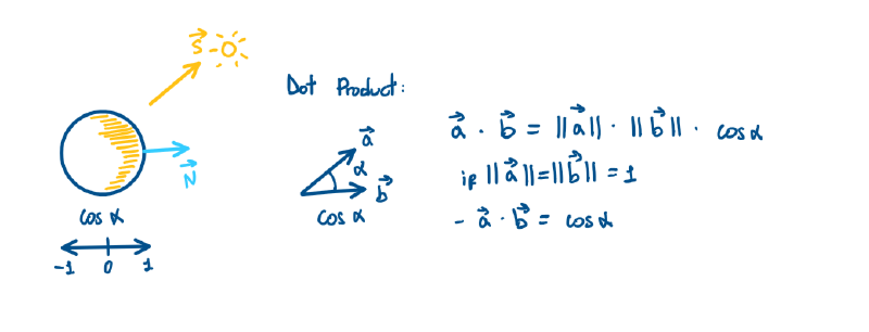
This cosine is what’s known as Lambert’s cosine law: the more aligned the normal is with the light direction (angle close to 0°), the more light the surface receives (cosine close to 1); the more obliquely the light hits (angle close to 90°), the less light reaches it (cosine close to 0). This simulates how the same amount of light gets “spread” over more or less surface depending on the angle of incidence.
vec3 sun_dir = normalize(vec3(0.6, 0.35, 0.5));
float sun_dif = clamp(dot(sun_dir, normal), 0.0, 1.0);
We do clamp(..., 0.0, 1.0) because, if the angle exceeds 90° (the surface faces away from the sun), the cosine becomes negative — and a negative amount of light doesn’t make physical sense. Clamping the value between 0 and 1 ensures that those surfaces simply receive no direct sunlight (they’re in self-shadow), instead of incorrectly “subtracting” light.
Sky Diffuse & Bounce Diffuse
To give the scene sky lighting and ground lighting (bounced light), we use the same technique as with sunlight.
We take the dot product of the normal with the vertical vector: positive (0,1,0) for the sky, negative (0,-1,0) for the ground bounce. We also remap the values so they range from 0 to 1, since the dot product returns a value between -1 and 1. In sky_dif we use 0.5 + 0.5*x, which splits the range symmetrically (half and half); in bou_dif we use 0.1 + 0.9*x, a different mix that gives more weight to the dot product (a stronger bounce when the normal faces directly toward the ground) and less weight to a constant base value. Finally, the result is clamped so it doesn’t fall outside the [0.0, 1.0] range.
float sky_dif = clamp(0.5 + 0.5*dot(normal, vec3(0.0, 1.0, 0.0)), 0.0, 1.0);
float bou_dif = clamp(0.1 + 0.9*dot(normal, vec3(0.0, -1.0, 0.0)), 0.0, 1.0);
This can be simplified, since multiplying by a unit vector that only has one active component simply “extracts” that component. So we can use normal.y directly instead of doing the dot product:
float sky_dif = clamp(0.5 + 0.5*normal.y, 0.0, 1.0);
float bou_dif = clamp(0.1 - 0.9*normal.y, 0.0, 1.0);
Hard Shadows
The idea of calculating shadows in raymarching is fairly simple. We reuse the same castRay function we used for the camera ray, but now we cast the ray from the object’s surface (slightly offset along the normal, so it doesn’t collide with itself due to precision errors) toward the light. If that ray hits something before reaching the light source, the original point is in shadow.
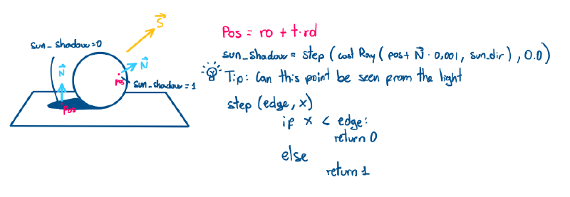
float sun_sha = step(castRay(pos + 0.001*nor, sun_lig, time), 0.0);
step(value, 0.0) — the step(edge, x) function returns 0.0 if x < edge, and 1.0 if x >= edge. Here it’s used “backwards” from how it’s usually read: step(castRay(...), 0.0) compares 0.0 against the result of castRay. Since in this simplified version castRay returns -1.0 when there’s no hit:
- If there’s no hit →
castRay(...) = -1.0→step(-1.0, 0.0) = 1.0(0.0 ≥ -1.0) → no shadow, full light. - If there’s a hit (it collides with something) →
castRay(...)is a positive distance (e.g.3.5) →step(3.5, 0.0) = 0.0(0.0 < 3.5) → full shadow.
Occlusion calculation
This function simulates a very subtle but important effect for realism: areas where nearby geometry surrounds a point (corners, folds, gaps between shapes) receive less ambient light, because part of that light gets blocked by the neighboring objects themselves. It’s what makes a character’s armpits, or the gap between two fingers, look slightly darker even without a shadow cast by the sun.
float h = 0.01 + 0.11*float(i)/4.0;
vec3 opos = pos + h*nor;
float d = map( opos, time ).x;
occ += (h-d)*sca;
For each of the 5 iterations, we take the surface point (pos) and move a distance h along the normal (nor) — that is, we move perpendicularly outward from the object. If there were nothing else nearby (a fully convex, unobstructed surface), the real distance to any other object at that point (d, obtained from map()) would be exactly h — because there’s no obstacle interfering.
But if there’s neighboring geometry nearby (a corner, a fold), the real distance d will be smaller than h, because something is in the way before that expected distance. The difference h - d measures exactly that: how much “closer than expected” there is surface there — the more neighboring geometry there is, the greater this difference.
return clamp( 1.0 - 2.0*occ, 0.0, 1.0 );
occ accumulates the weighted (h-d) differences: the higher occ is, the more “enclosed” the point is by neighboring geometry. By doing 1.0 - 2.0*occ, we invert the scale: if occ is high (a lot of occlusion), the result approaches 0 (little ambient light); if occ is low or zero (unobstructed surface), the result approaches 1 (full ambient light). The clamp ensures the result always stays in the [0, 1] range, since the multiplication by 2.0 is an arbitrary factor to amplify the effect (an artistic adjustment, not a physical one) and could push the value out of range.
Camera (Look-at)
To build a camera that always looks at a fixed point. A target is defined, and from there the camera’s position (which will also be the ray origin, ro).
With the target and the origin we can define the “forward” vector (ww), normalized: it’s simply the direction from ro toward target.
To generate the “right” vector (uu), we take the cross product of the forward vector and the world’s vertical vector. The cross product between two vectors gives a third vector perpendicular to both. By doing cross(ww, vec3(0,1,0)) (forward × world-up), we get a vector perpendicular both to “where the camera is looking” and to the world’s vertical axis — which is exactly the camera’s “right” direction.
Once we have the forward and right vectors, we repeat the process to get the camera’s actual “up” vector (vv). We can’t simply reuse vec3(0,1,0) as up, because if the camera looks up or down, that “world up” would no longer be perpendicular to the other two axes. That’s why we recompute it with cross(uu, ww), ensuring the three vectors form a perfectly orthogonal basis with each other.
        vec3 target = vec3(0.0, 0.75, 0.4);
        // ray origin
        vec3 ro = target + vec3(1.5 * sin(an),-.1,1.5 * cos(an));

        vec3 ww = normalize(target - ro);
        vec3 uu = normalize(cross(ww, vec3(0,1,0)));
        vec3 vv = normalize(cross(uu,ww));
These vectors form the basis for building the direction of each pixel’s ray:
// This normalize the coordinates from [-aspectRatio,-1] to [aspectRatio, 1]
vec2 p = (2.0*(fragCoord+offset) - iResolution.xy) / iResolution.y;
vec3 rd = normalize(p.x*uu + p.y*vv + 1.8*ww);
Here p.x and p.y are the normalized pixel coordinates on screen: p.y ranges from -1 to 1, while p.x ranges from -aspectRatio to aspectRatio (where aspectRatio is the screen’s width divided by its height). These coordinates are combined with the camera’s uu (right), vv (up), and ww (forward) axes to build the ray’s direction in world space — that is, “how much I deviate right/up from the center of the view, and how much I advance forward.” The 1.8 multiplying ww controls the field of view (FOV): the larger that number, the more “zoom” (narrower field of view); the smaller, the wider the angle (broader FOV).
Simple scene
This is the final result: Iñigo Quilez’s shader with a basic scene that brings together the elements we’ve covered — the raymarching loop, the normal calculation, and the lighting combining sun, sky, bounce, and shadows.